- Who We Are
- What We Do
- Systems Engineering
- Program Acquisition and Technical Assistance
- Testing and Evaluation
- Professional Development Training and Tools
- LinkPlan Overview
- Equipment Training Overview
- Professional Training Courses
- Systems Acquisition
- Satellite Communications - Introduction
- Satellite Communications - Advanced
- SATCOM Systems Engineering - Introduction
- SATCOM Systems Engineering - Advanced
- Propagation and Impairments
- Satellite Architecture and Design
- Terminal Architecture and Design
- LinkPlan™ Link Analysis - Introduction
- LinkPlan™ Link Analysis - Advanced
- UHFPlan™ Link Analysis
- Careers
- Working With Us
- Contact Us
LinkPlan™ is a link planning and analysis program for satellite communications networks, using published data for commercial, DoD, NATO, and Allied satellites and terminals. Version 9.98 (January 2010) is the latest version for Excel 2003 and earlier; Version 11 (October 2011) is the latest version for Excel 2007/2010.
Features
- Performs link engineering and analysis for point-to-point and hub-spoke SATCOM networks, to include control links if desired, for systems operating in C-, X-, Ku-, and Ka-Band linear transponders
- Uses typical values for military (DSCS III, Wideband Global SATCOM, NATO, Skynet, XTAR) and commercial (INTELSAT, SES, EUTELSAT, and Regional) satellites
- Provides a comprehensive database of military and commercial earth terminals
- Computes rain margins using a parametric model based on the Crane Rain Model statistics
- Computes link degradation effects from HPA IMD, satellite IMD, co-channel interference, and adjacent satellite interference; validates scenarios against ITU limits for off-axis EIRP density and maximum power flux density
- Allows the user to optimize links based on available terminal and satellite power/bandwidth
- Supports definition of custom satellites and earth terminals for design of future systems
- Provides calculators to support General SATCOM, RF and Microwave, Satellite Visibility, NORAD Two Line Elements, Intermodulation Distortion, Integrated Phase Noise, Downlink Rain Fade, ITU Rain Model, and Solar Conjunction computations
Dialogues and Windows
LinkPlan offers numerous dialog boxes and windows to guide the user through the link analysis process. Some of them are highlighted below.
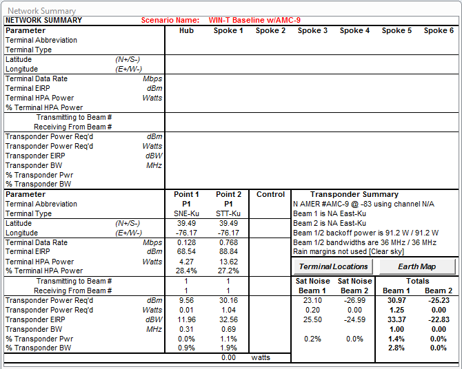
The Network Summary Window provides a summary of the defined satellite and terminal scenario and results.
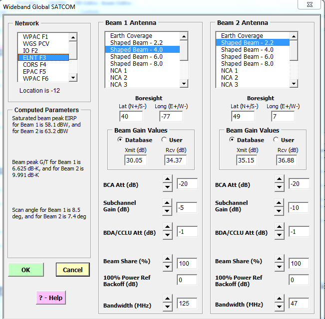
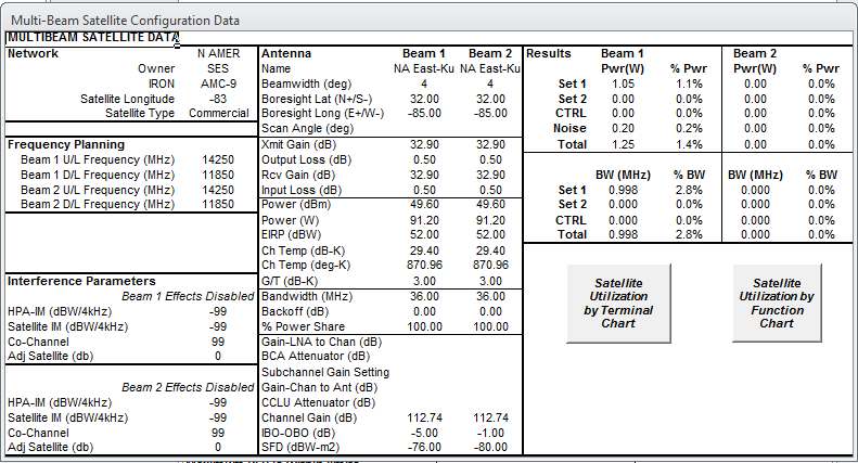
The WGS Satellites dialog box allows the user to select the appropriate WGS satellite, and specify antenna and transponder settings. Typical values for the operational satellites are included in the database. Results are displayed in the satellite window. This dialog box is typical for any of the satellite families included in LinkPlan™.
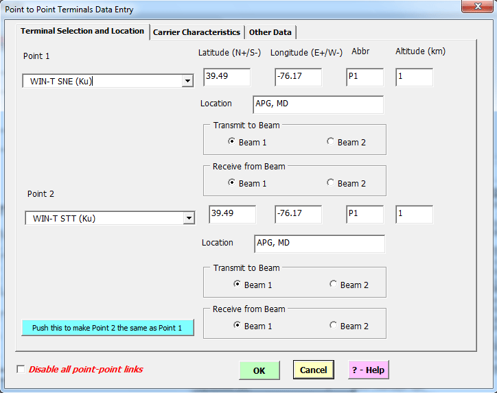
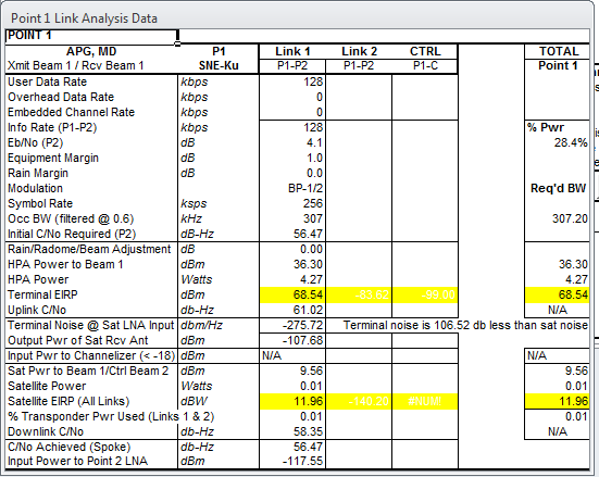
The Point-to-Point Terminals Data Entry dialog box has three tabs associated with it: Terminal Selection, Carrier Characteristics, and Other Losses. The Terminal Selection tab allows the user to select the desired terminal type, enter location data (if mobile), location site, and a terminal abbreviation. The Carrier Characteristics tab allows the user to enter link data rates, Eb/No and margin; and to select the appropriate modulation and coding scheme. The Other Losses tab allows the user to enter miscellaneous link-related losses. Results are displayed in the appropriate link analysis window.
Use of LinkPlan™
LinkPlan™ software is designed to be a training tool. The software is provided "as is" as part of selected Systek training programs, and is not warranted in any form or fashion. It is not intended for commercial use, other restrictions apply, and distribution is prohibited without written permission from Systems Technologies, Inc. To secure permission, contact Systek.


